Features
? Up to 25.78125 Gbps data rate
? Up to 5 meter transmission
? Hot-pluggable SFP 20PIN footprint
? Improved Pluggable Form Factor(IPF)
compliant for enhanced EMI/EMC
performance
? Compatible to SFP28 MSA
? Compatible to SFF-8402 and SFF-8432
? Temperature Range: 0~ 70 °C
? RoHS Compatible
Benefits
? Cost-effective copper solution
? Lowest total system power solution
? Lowest total system EMI solution
? Optimized design for Signal Integrity
Applications
? 25G Ethernet
Product Description
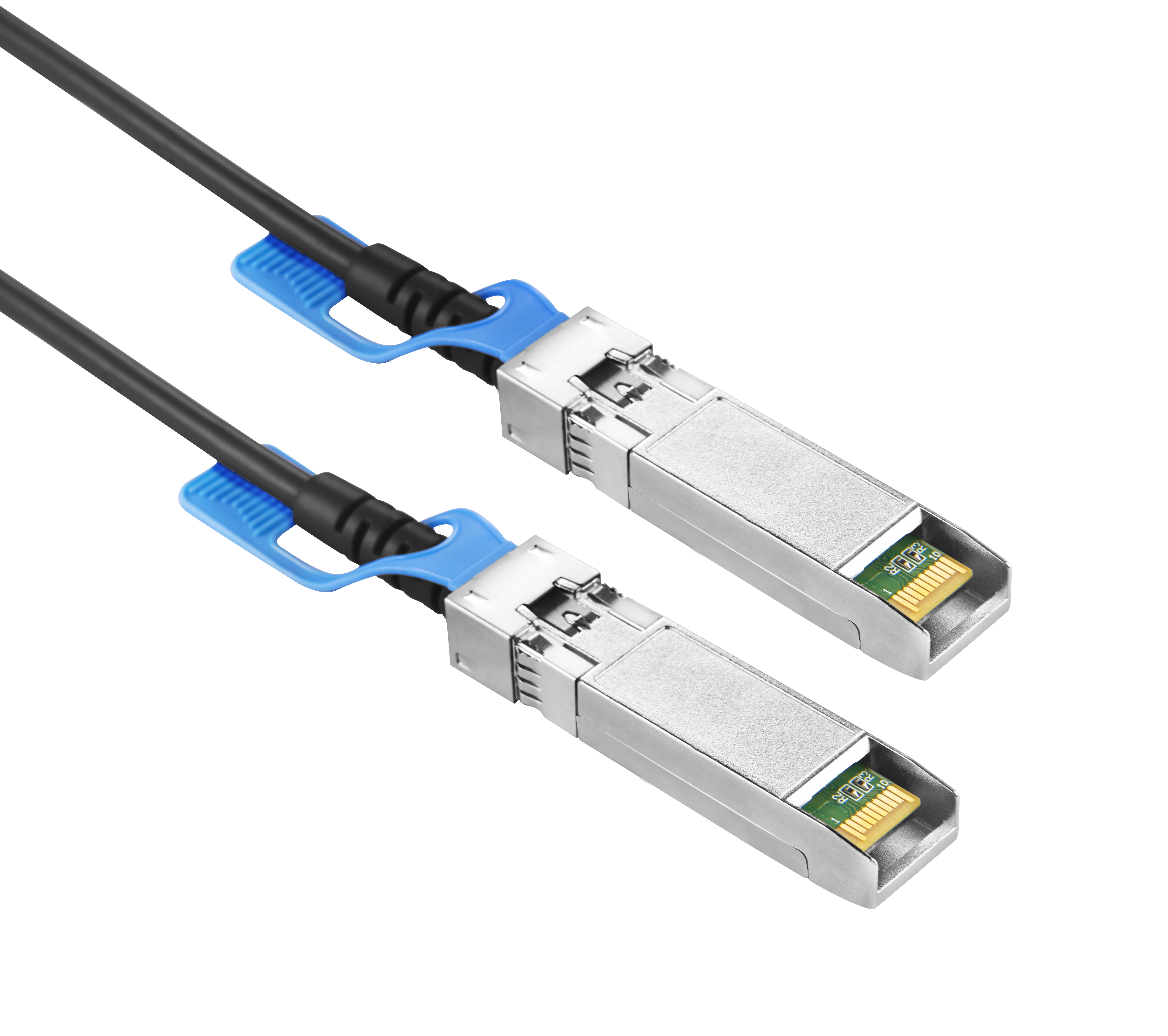
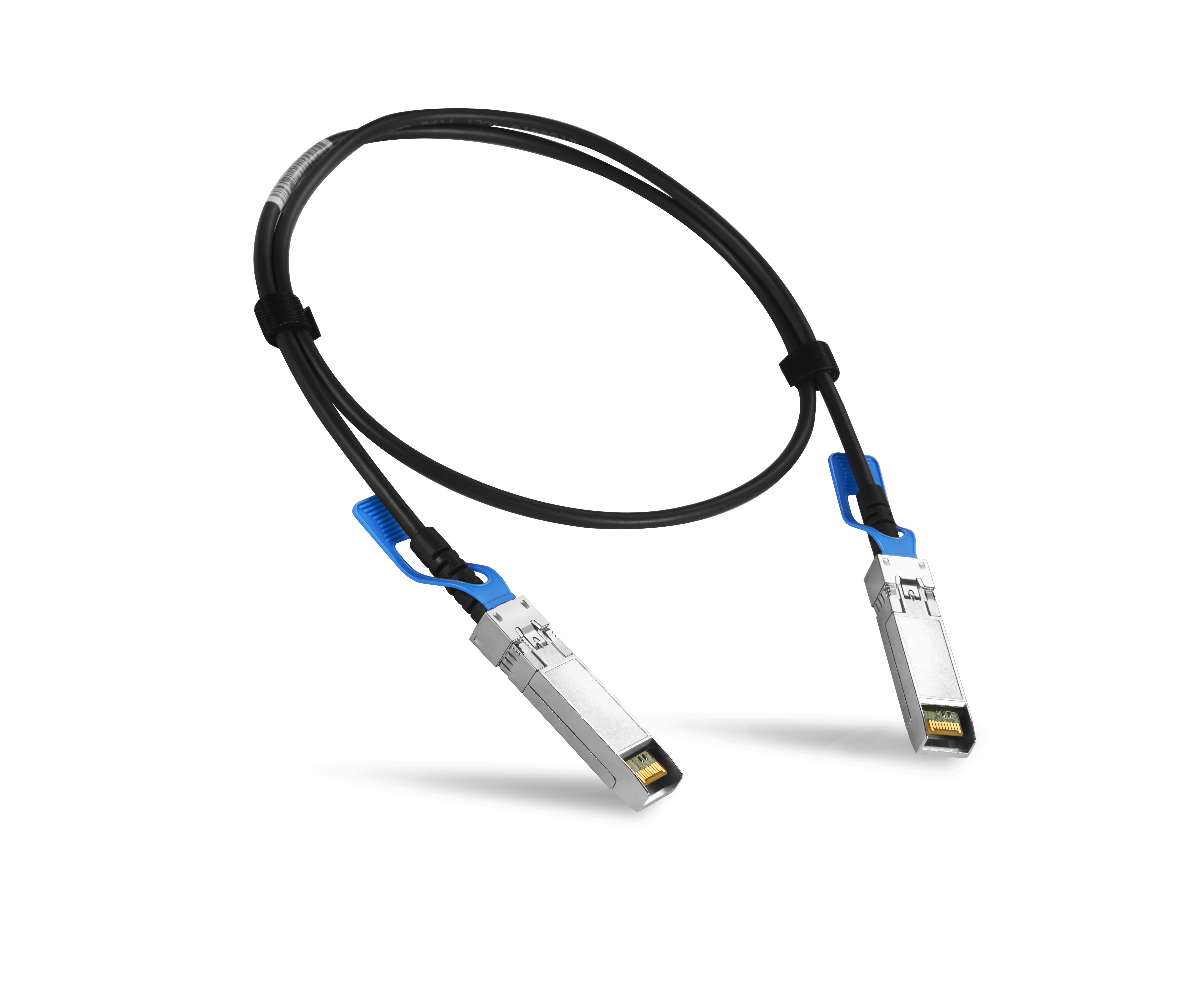
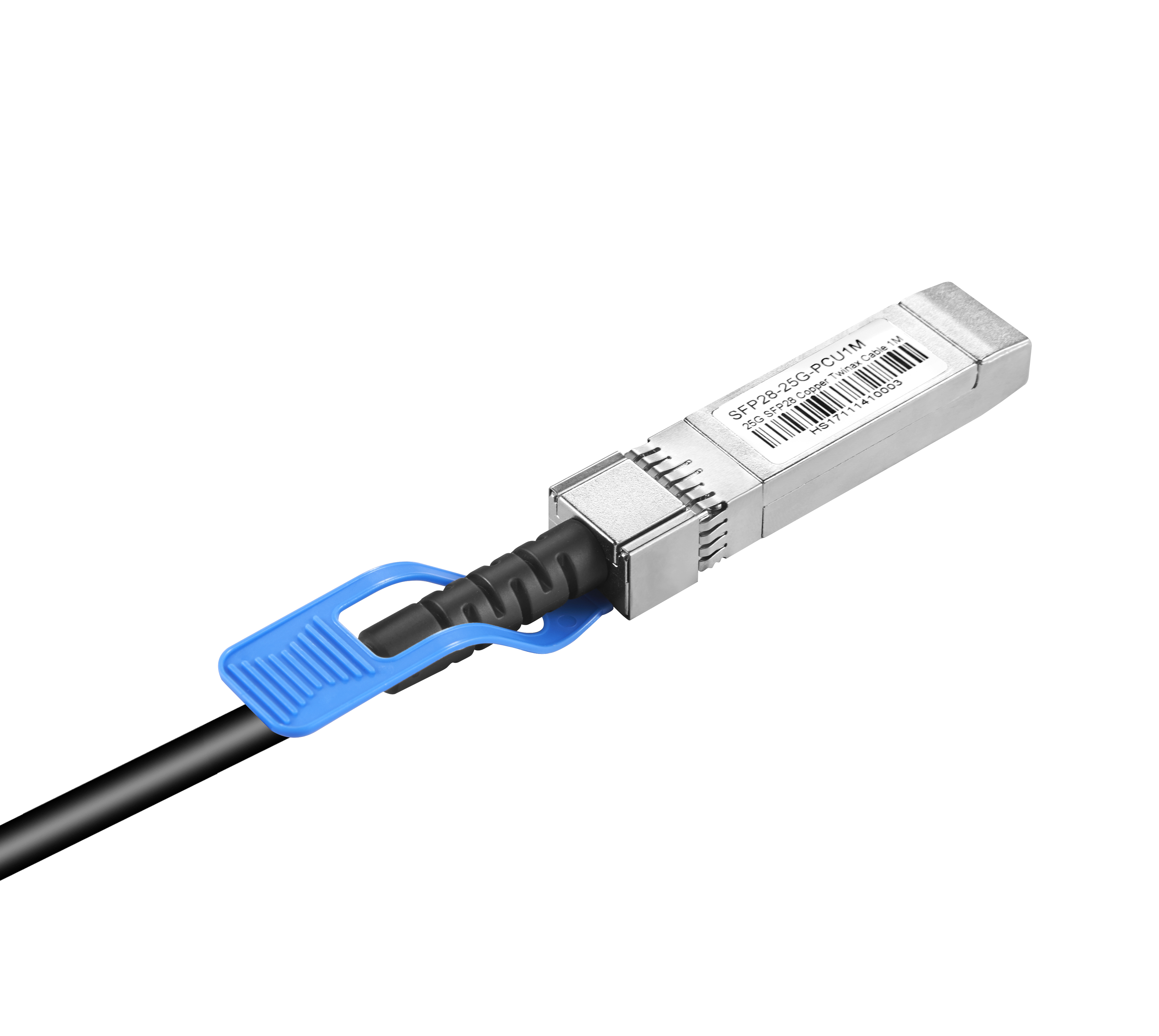
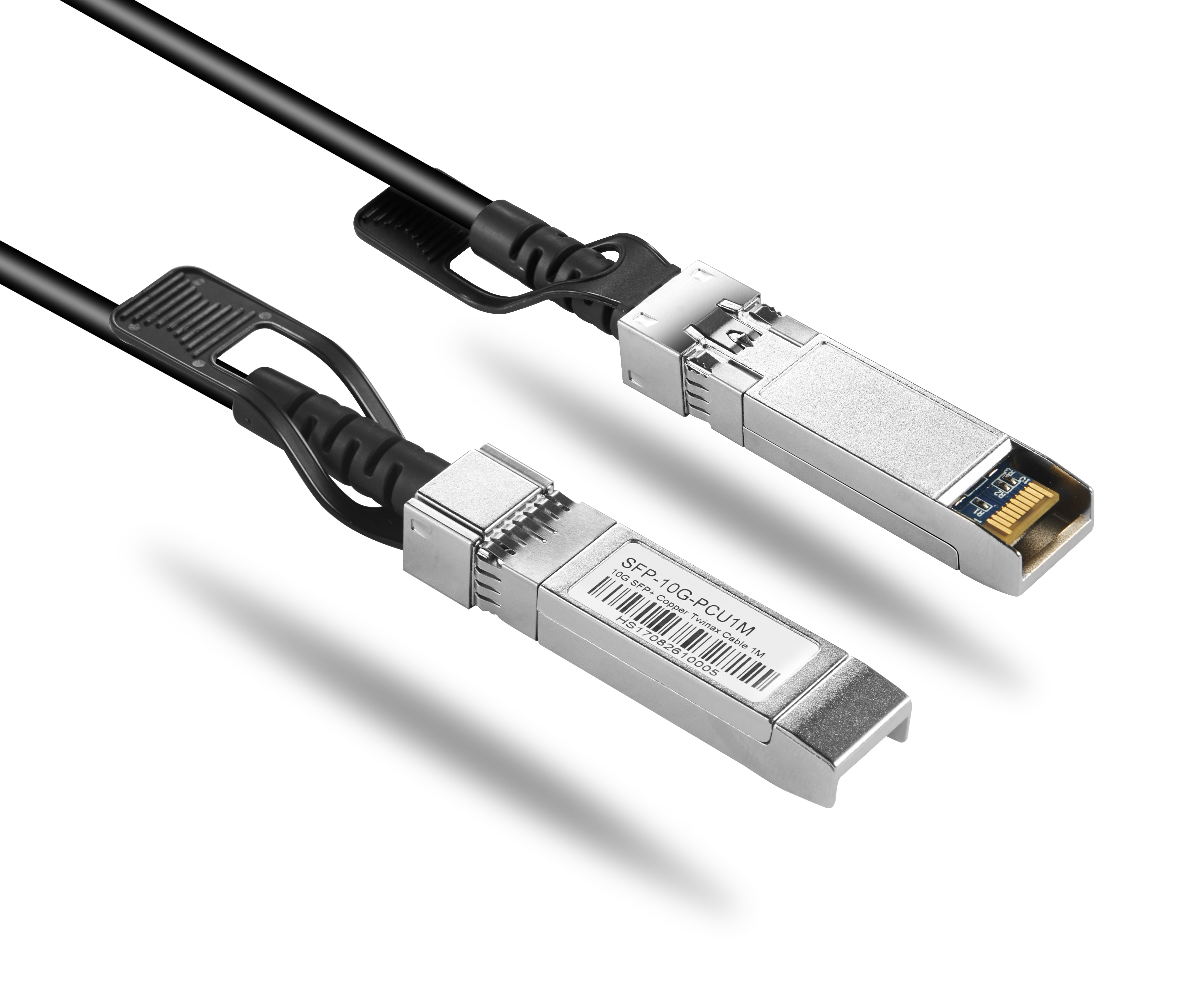
? The SFP28 passive cable assemblies are high performance, cost effective I/O solutions for 25G Ethernet. SFP28 copper cables allow hardware manufactures to achieve high port density, configurability and utilization at a very low cost and reduced power budget
High Speed Characteristics
Parameter | Symbol | Min | Typical | Max | Unit | Note |
Differential Impedance | TDR | 90 | 100 | 110 | ? |
|
Insertion loss | SDD21 | -22.48 |
|
| dB | At 12.8906 GHz |
Differential Return Loss | SDD11 SDD22 |
|
| See 1 | dB | At 0.05 to 4.1 GHz |
|
| See 2 | dB | At 4.1 to 19 GHz |
Common-mode to common-mode output return loss | SCC11 SCC22 |
|
| -2 | dB | At 0.2 to 19 GHz |
Differential to common-mode return loss | SCD11 SCD22 |
|
| See 3 | dB | At 0.01 to 12.89 GHz |
|
| See 4 | At 12.89 to 19 GHz |
Differential to common Mode Conversion Loss | SCD21-IL |
|
| -10 | dB | At 0.01 to 12.89 GHz |
|
| See 5 | At 12.89 to 15.7 GHz |
|
| -6.3 | At 15.7 to 19 GHz |
Notes: 1. Reflection Coefficient given by equation SDD11(dB) < -16.5 + 2 × SQRT(f ), with f in GHz 2. Reflection Coefficient given by equation SDD11(dB) < -10.66 + 14 × log10(f/5.5), with f in GHz 3. Reflection Coefficient given by equation SCD11(dB) < -22 + (20/25.78)*f, with f in GHz 4. Reflection Coefficient given by equation SCD11(dB) < -15 + (6/25.78)*f, with f in GHz 5. Reflection Coefficient given by equation SCD21(dB) < -27 + (29/22)*f, with f in GHz |
Pin Descriptions
SFP28 Pin Function Definition
Pin | Logic | Symbol | Name/Description | Notes |
1 |
| VeeT | Transmitter Ground |
|
2 | LV-TTL-O | TX_Fault | N/A | 1 |
3 | LV-TTL-I | TX_DIS | Transmitter Disable | 2 |
4 | LV-TTL-I/O | SDA | Tow Wire Serial Data |
|
5 | LV-TTL-I | SCL | Tow Wire Serial Clock |
|
6 |
| MOD_DEF0 | Module present, connect to VeeT |
|
7 | LV-TTL-I | RS0 | N/A | 1 |
8 | LV-TTL-O | LOS | LOS of Signal | 2 |
9 | LV-TTL-I | RS1 | N/A | 1 |
10 |
| VeeR | Reciever Ground |
|
11 |
| VeeR | Reciever Ground |
|
12 | CML-O | RD- | Reciever Data Inverted |
|
13 | CML-O | RD+ | Reciever Data Non-Inverted |
|
14 |
| VeeR | Reciever Ground |
|
15 |
| VccR | Reciever Supply 3.3V |
|
16 |
| VccT | Transmitter Supply 3.3V |
|
17 |
| VeeT | Transmitter Ground |
|
| 18 | CML-I | TD+ |
| Transmitter Data Non-Inverted |
|
| 19 | CML_I | TD- |
| Transmitter Data Inverted |
|
| 20 |
| VeeT |
| Transmitter Ground |
|
1. | Signals not supported in SFP+ Copper pulled-downto VeeT with 30K ohms resistor |
|
2. | Passive cable assemblies do not support | LOS and TX_DIS |
|
Mechanical Specifications
The connector is compatible with the SFF-8432 specification.
Length (m) | Cable AWG |
1 | 30 |
2 | 30 |
3 | 30/26 |
4 | 26 |
5 | 26 |
Regulatory Compliance
Feature | Test Method | Performance |
Electrostatic Discharge (ESD) to the Electrical Pins | MIL-STD-883C Method 3015.7 | Class 1(>2000 Volts) |
Electromagnetic Interference(EMI) | FCC Class B | Compliant with Standards |
CENELEC EN55022 Class B |
CISPR22 ITE Class B |
RF Immunity(RFI) | IEC61000-4-3 | Typically Show no Measurable Effect from a 10V/m Field Swept from 80 to 1000MHz |
RoHS Compliance | RoHS Directive 2011/65/EU and it's Amendment Directives 6/6 | RoHS 6/6 compliant |


